Lecture notes – Chapter 5
Map coordinates based on map projections
The maps can satisfy both military and civil purposes in the geographic location, orientation and navigation, furthermore it is applied in planning and construction of engineering projects. The location requires coordinates on the map. On large scale maps, even if the graticule is indicated, it is mostly composed of imperceptibly curved lines. With only exceptions, they do not offer an opportunity to determine the accurate geographic coordinates. Therefore – both the printed paper maps and the screen maps – in most of the cases have a planar rectangular map coordinate system, even if it is not marked on the map. The coordinates of a point on the map can be determined by linear measuring tools (mostly by ruler). With the help of measured rectangular map coordinates of a point, its real Earth location can be inferred back by the map projection.
There are world wide map coordinate systems, in other cases the coordinate system is extended to a country or an empire, or it is used locally (e.g., in an urban or an industrial area). (On a map sheet an own separate coordinate system can be interpreted, too.)
Sometimes a planar polar coordinate system can be created on a map, mostly as an intermediate system.
Graticule and grid lines
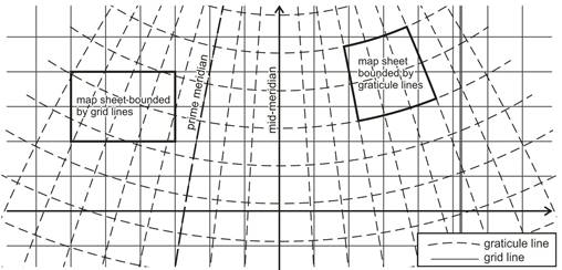
The graticule lines and the rectangular coordinate lines (in other words the grid lines on the map) generally are not parallel to each other. The map graticule having at least one prescribed axis of reflection symmetry coinciding with a meridian, the so called „mid-meridian” or „central meridian” (mostly not identical with the prime meridian), which runs along the midline of the area to be represented. The direction of this axis is the „grid north”, while the tangent of the meridian gives the „true north” (in other words „geodetic north”) at every point of the map. In most instances the topographic map sheets are bounded by graticule lines, while some kinds of cadastral maps are bounded by grid lines.
Transformation of coordinates from the Earth to the map by map projection
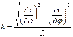
The map coordinates are in mathematical connection with the mapped Earth coordinates. This mapping – the map projection – comes true by the projection equations (actually functions satisfying the mathematical conditions of injectivity, twice continously differentiability and describability by formulae or series) which assign the map coordinates x, y to the coordinates j, l in case of spherical reference surface:
![]()
![]() .
.
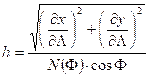
If the same mapping functions are referred to the metacoordinates j*, l*, the mapping
![]()
![]()
considered as identical to the previous one. (In this case, the map coordinates are calculated mostly in two steps from the Earth coordinates by inserting the metacoordinates: j, l ® j*, l* ® x,y.) The previous version is called normal (polar) projection, and the latter is transverse (equatorial) or oblique projection, whether the metapole is situated on the equator (transverse) or anywhere except the pole and the equator (oblique).
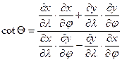
The geographic coordinates can be obtained from the rectangular map coordinates by the inverse of the projection equations. They are in case of sphere:
![]()
![]()
or
![]()
![]() .
.
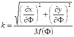
In case of ellipsoidal coordinates F, L the projection equations take the general shape
![]()
![]()
and the inverse of the projection equations:
![]()
![]()
The main classes of the map projections
The classification of the map projections is founded on the geometric character of the graticule or metagraticule on the map. The category of the conic projections contains the azimuthal, cylindrical and conical projections with meridians as straight lines, and parallels as circles, parallel straight lines or circular arcs. The category of the non-conic projections covers the pseudoazimuthal, pseudocylindrical, pseudoconical (included the polyconic) and other – „miscellaneous” – projections (without any usual geometric graticule restriction). The large scale maps (so the maps of the GIS) are prepared predominantly in conic projections. The geocartography uses both conic and non-conic projections.
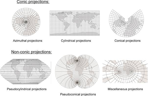
Some kinds of projections, so the normal azimuthal, cylindrical and conical projections result in rectangular graticule. A few conic projections in transverse and oblique versions, and some of non-conic projections also have this property.
Map distortions
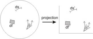
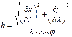
In the course of the planar representation of the Earth surface objects (so arcs, figures, directions), some of their sizes (lengths, areas, angles) change which makes the measuring the shape sizes and map coordinates difficult in practice, mainly for the purpose of determining the original extents. These are mathematically formulated in the so called map distortions, viz. the linear scale l, the area scale p and the angular distortion i, one after the other:
![]() ,
, ![]() ,
, ![]()
where ds, ds’, df, df’ are infinitesimal quantities, in addition d and d’ are the corresponding angles on the reference surface and on the map plane, respectively.
The consequence of the fundamental statement of the differential geometry, the Gauss’s Theorema Egregium is that the Earth cannot be represented on a map without distortions. Specifically, the linear scale cannot be eliminated, but there are projections without area distortions (the so called equal-area or equivalent projections), or similarly without angular distortions (the so called conformal projections), keeping the real area or angular footing, respectively. The so called aphylactic projections are neither conformal, nor equivalent. Both the military and the civil topography (inclusive of cadastral cartography) use generally conformal projections, many kinds of thematic maps are created in equal-area projection, and most of the chorographic maps has an aphylactic projection.
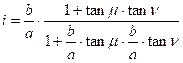
According to Tissot’s construction, the area, scale and angular distortions at every point of the map can be calculated with the help of maximum and minimum linear scales (denoted by a and b), whose direction is perpendicular either on the reference surface or on the map. These are determined by the graticule distortions, namely the linear scale h along the parallel, the linear scale k along the meridian, and the angle Q between the graticule lines, in accordance with the next formulae:
![]()
and ![]()
where in the case of projections based on a reference sphere of radius R:
 ,
,  ,
,
 and
and ![]() .
.
The scale distortions along the graticule lines in case of ellipsoidal projection:
 ,
, 
The formula for the area scale p is:
![]()
Denoting the angle between the direction of the maximum scale distortion a and a questionable direction by d, the linear scale along the latter direction is:
![]()
If one of the arms of an arbitrary angle coincides with the direction of the maximum linear scale a, then the angular distortion i refering to this angle:
![]() ,
,
that is in this special case, the angular distortion does not depend on the angle d.
If neither of the arms of the angle d coincides with the direction of the maximum linear scale a, then writing the angle d as difference of the angles m and n (in formula d=m-n) where one of the arms of both m and n coincide with the direction of a, then the angular distortion i:
In effect the distortions are determined ultimately by the projection equations.
In consequence of the points described above, the conformality that is the equality d’=d for every angle d on the reference surface, can be given by the equation
![]()
and similarly the equivalency by
![]() .
.
In case of rectangular graticule (or metagraticule) the maximum and minimum linear scales come up along the direction of graticule lines, therefore they can be calculated by simpler formulae. Then the equation of the conformality is
![]() ,
,
and the equation of the equivalency is
![]()
concerning the graticule (or the metagraticule, in case of transverse or oblique projections).